Customized Bushings: Tailoring to Unique Demands
The Science Behind Plain Bushing Materials: A Comprehensive Guide to Performance and Applications
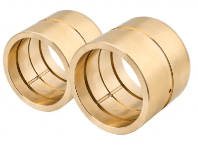
Plain bushings, also known as sleeve bearings, play a crucial role in the functioning of various machinery by significantly reducing friction, providing necessary support for loads, and ensuring proper alignment of moving parts within mechanical systems. The overall effectiveness of these bushings is highly dependent on the careful selection of materials used in their construction. In this article, we will take a closer look at the most commonly used bushing materials in the industry, exploring their unique properties and characteristics, as well as how they interact with the specific operational demands placed on them to guarantee optimal performance in various applications. The examination will highlight factors such as wear resistance, load-bearing capabilities, and thermal stability, which are essential for maintaining efficiency and longevity. To further illustrate these concepts, we include a detailed close-up view of a self-lubricating slide bearing bushing, showcasing its ability to operate maintenance-free even under high-load conditions. This example serves to emphasize the advancements in bushing technology, enabling machines to function smoothly and reliably with minimal intervention.
Bronze Sleeve Lubrication: A Deep Drive into Groove Design for high - Viscosity Ouls
Oil Groove for High - Viscosity Oil Deep Groove Bushing:
Comparing Oil Groove Patterns for Viscous Fluids
The geometry of your groove determines everything. An effective design will actively pull in and distribute thick oil, while a poor design will block it.
| Groove Type | Diagram/Description | Performance with High-Viscosity Oil |
| Single Straight Groove | A simple axial groove. | Poor. Fails to distribute oil circumferentially. Oil will not travel far along the shaft. |
| Circular / “O” Groove | A single circular groove in the center. | Poor to Fair. Good for distributing oil around the shaft at the inlet, but poor at moving it along the shaft’s length. |
| Figure-Eight / Double-O | Intersecting or parallel circular grooves. | Fair to Good. Better axial distribution than a single “O” groove, but can still struggle to push thick oil to the bearing ends. |
| Single Spiral Groove | A continuous helical groove. | Excellent. Acts as a pump, actively drawing in viscous oil and forcing it along the entire length of the bearing. |
As the chart shows, for rotating shafts using high-viscosity oil, the spiral groove is the undisputed champion.
A Deep Dive into Spiral Groove Design
A spiral groove transforms the bearing from a passive component into an active lubrication pump. As the shaft rotates, it forces the viscous oil along the helical path, ensuring complete and consistent coverage. However, a poorly designed spiral can be worse than no groove at all.
Here are the critical design considerations:
1. Direction of the Spiral (The Golden Rule)
This is the most crucial element. The spiral must be designed to pump oil from the inlet and along the bearing length.
- Rule: For a unidirectional shaft, the groove spiral should be opposite to the direction of rotation.
- Example: If the shaft rotates Clockwise (CW), you need a Left-Hand Spiral. If it rotates Counter-Clockwise (CCW), you need a Right-Hand Spiral.
(Conceptual Diagram: A clockwise shaft rotation with a left-hand spiral creates a pumping action, distributing oil throughout the bearing.)
For bidirectional rotation, a double-helix (crisscrossing spirals) is the ideal, though more complex, solution.
2. Groove Geometry (Width and Depth)
With high-viscosity oil, you need wider and deeper grooves to reduce flow resistance.
- Width: Too narrow, and the oil can’t enter. Too wide, and you sacrifice too much load-bearing surface area. A good starting point is a width of 5-10% of the bearing’s inner diameter.
- Depth: Similar to width, depth must be sufficient to act as a reservoir. A depth of 2-5% of the inner diameter is a common baseline.
- Edge Blending: CRITICAL! All groove edges must be chamfered or rounded. Sharp edges will scrape oil off the shaft, destroying the hydrodynamic film you’re trying to create.
3. Pitch of the Spiral
The pitch is the axial distance for one full 360° turn of the spiral.
- Finer Pitch (more turns): Better for shorter bearings or when extremely uniform distribution is needed.
- Coarser Pitch (fewer turns): Suitable for longer bearings to move oil efficiently from end to end.
4. Oil Inlet Location
The oil inlet hole must feed directly into the start of the spiral groove, preferably in an unloaded area of the bearing (e.g., the “top” of a horizontally loaded bearing). For long bearings, multiple inlets feeding the same spiral groove can dramatically improve performance.
Your Design Checklist Before Manufacturing
Before you send a drawing to the machine shop, answer these questions. The answers will dictate the ideal groove parameters.
- Bearing Dimensions: What are the Inner Diameter (ID), Outer Diameter (OD), and Length? (This sets the baseline for all other calculations).
- Operating Load & Speed (RPM): How much force is on the bearing and how fast is it spinning? (This determines the required strength of the oil film).
- Oil Viscosity: What is the specific ISO VG number (e.g., VG 460, VG 680)? (“High” is not enough information).
- Direction of Rotation: Is it unidirectional or bidirectional? (This determines the spiral direction).
- Space Constraints: Are there limitations on groove depth due to wall thickness?